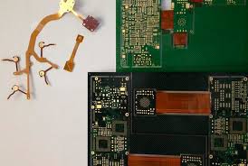
rigid flex boards
Rigid flex PCBs are becoming more and more popular as engineers look for ways to increase device efficiency, functionality and performance while decreasing size and overall system weight. These innovative technologies are able to deliver on the stability of rigid PCBs while adding flexibility and reliability in tight spaces, making them ideal for portable and foldable devices. Despite their many benefits, rigid flex boards can be confusing for designers as they attempt to understand the limitations and advantages of this technology. To help demystify rigid flex technology, this blog will explore how they differ from traditional rigid PCBs and highlight the key areas of design consideration.
Unlike flexible circuit boards, which utilize the same basic materials as rigid PCBs, rigid flex board have additional layers that make them more rigid and stable. They are constructed through a process called copper foil lamination, where a layer of flexible base material is laminated to a layer of thin copper foil. This foil is then etched and plated with copper to create the conductive traces for the circuits. To create the circuit patterns, photolithography is used to apply a mask that selectively exposes the copper foil for etching and plating.
Once the copper traces have been created, the entire structure is annealed to make it more durable. This annealing step is also important for preventing solder joint failure, which can be caused by the mechanical stresses of repeated bending and flexing of the circuit board. The annealing process is performed in an oven with specific temperature and time settings that ensure the optimum result.
How does solder joint reliability differ in rigid flex boards?
As the rigid flex circuit is flexed and bent, the solder joints experience mechanical stress that can cause a variety of issues. The most significant issue is the thermal displacement of the flex substrate, which can cause solder failure due to excessive stress on the joints. The flex substrate can also shift during a vibration test, which increases the stress on the solder joints and may lead to failure. To prevent this, it is essential to use the correct soldering techniques and a proper anneal.
Rigid flex circuits are also more susceptible to stress from vertical acceleration and vibration than conventional rigid PCBs, so it is crucial to design them properly to ensure the mechanical integrity of the components. This can be achieved by designing the rigid portions to withstand vertical and horizontal acceleration with a specified amplitude. Rigid-flex circuits can also be designed to include a redistribution layer between the rigid and flex sections.
Another important factor to consider when evaluating rigid flex circuits is their ability to meet the requirements of a particular application. For example, if the product will be subjected to high-speed signal processing, then it is critical that the circuit board can support these signals. For this reason, it is necessary to test and inspect the rigid-flex circuit to ensure that it can handle these loads. In addition, the rigid-flex circuit board must be able to withstand the effects of environmental conditions like temperature and humidity.